Full Wave Rectifier: Which Ripple and Efficiency Values to Write
A full wave rectifier has an exact ideal ripple factor of 0.4834 and efficiency of 81.06%, though printed values vary. Write your textbook figure in exams, the exact one in lab reports.

By Rahul Jeewani, Founder · Updated 9 Nov 2026
Key takeaways
- The exact ideal ripple factor is 0.4834 (48.34%) and the exact efficiency is 81.06%. In an exam write the value your textbook prints. In a lab report or viva write the exact value. In both cases show the formula.
- A full wave rectifier uses both half-cycles, so the output frequency is twice the mains frequency (100 Hz from 50 Hz) and the ideal average output is 2Vm/π ≈ 0.637 Vm, where Vm is the peak input voltage.
- A bridge needs diodes rated for only Vm but loses two diode drops. A centre-tap needs diodes rated for 2Vm but loses one drop.
- Using 2(Vm − Vd)/π for the average output, where Vd is the total diode drop in the current path, overstates it. In our 12 V example it is high by about 2.5% for the centre-tap and 5% for the bridge.
In this article
- 1What does a full wave rectifier do to an AC input?
- 2Centre-tap or bridge: which needs the higher PIV and loses more voltage?
- 3Why do printed ripple factors and efficiencies differ?
- 4How do you solve a rectifier numerical with diode drops?
- 5Which six checks should you run on any rectifier numerical?
- 6How much does a smoothing capacitor reduce the ripple voltage?
- 7How can RG Lectures help you prepare Physics for MHT-CET?
- 8Frequently asked questions
Look up the ripple factor of a full wave rectifier and the answer changes by page: 0.482 on one, 48.1% on another. Look up the efficiency and you meet 81.13% or 81.2%. All of them describe the same ideal circuit, one that turns alternating current (AC) into current that flows one way.
The gap is small, but it matters when a numerical offers close options, or when you have to defend a number in a viva (an oral exam) or a lab report. Worked from the formulas, the exact values are 0.4834 and 81.06%. Below, you get those derivations and a clear rule for which printed figure to write.
Marks also leak through the diode drop, the small voltage each conducting diode takes. A bridge loses two drops and a centre-tap loses one. In our 12 V example the usual shortcut formula overstates the output by about 2.5% for the centre-tap and 5% for the bridge.
What does a full wave rectifier do to an AC input?
A full wave rectifier converts AC into pulsating DC by letting current flow through the load in the same direction during both the positive and negative half-cycles. That doubles the pulse rate. At 50 Hz mains, the output ripple is at 100 Hz, because the output frequency is 2 × the line frequency.
There are two builds:
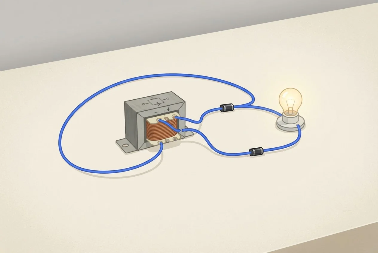
- Centre-tap: two diodes and a transformer whose secondary has a middle connection. A "12-0-12" label means 12 V rms on each side of the centre. Each diode conducts on alternate half-cycles.
- Bridge: four diodes and no centre connection. Two diodes conduct on each half-cycle.
Here Vm is the peak voltage, and rms (root mean square) is the steady-voltage equivalent of an AC signal, Vm/√2. For the ideal circuit, the average output is Vav = Vdc = 2Vm/π, and the load rms is Vrms = Vm/√2 (Virtual Labs, full wave rectification theory). Since 2/π = 0.6366, that is about 0.637 Vm.
Two terms that come up next. The form factor is Vrms/Vav. The ripple factor measures how much AC is left in the output, as the AC component divided by the DC component. Padhna Aasaan Hai: if you can say those two in one line each, the rest is substitution.
Centre-tap or bridge: which needs the higher PIV and loses more voltage?
A centre-tap needs diodes rated for twice the peak voltage and loses one diode drop. A bridge needs diodes rated only for the peak voltage but loses two drops, about 1.4 V at 0.7 V per diode. PIV (peak inverse voltage) is the largest reverse voltage a diode must block while it is off.
| Item | Centre-tap | Bridge |
|---|---|---|
| Diodes | 2 | 4 |
| Transformer | Centre-tapped secondary | Plain secondary |
| PIV needed | ≥ 2Vm | ≥ Vm |
| Diode drops in the path | 1 | 2 (about 1.4 V at 0.7 V each) |
| Output frequency | 2f | 2f |
PIV figures are from Virtual Labs. Two diodes conduct in series on each half-cycle in a bridge, so it costs you more in a low-voltage supply. At 5 V peak the extra 0.7 V is 14% of the peak voltage. At 100 V peak it is 0.7%.
Frequency does not separate the two circuits: both give 2f. If a question asks "which gives 100 Hz", the answer is both.
Why do printed ripple factors and efficiencies differ?
Printed values differ because rounding happens at different steps. The exact ripple factor of an ideal full wave rectifier is 0.4834, and 0.482 is what you get when the form factor is rounded to 1.11 before squaring. The other printed figures (48.1%, 81.13%, 81.2%) appear to come from rounding at other steps, and the sources do not say which step each used.
Our working, using the Virtual Labs formulas:
- Form factor = Vrms/Vav = (Vm/√2) ÷ (2Vm/π) = π/(2√2) = 1.1107.
- Ripple factor = √(FF² − 1) = √(1.2337 − 1) = 0.4834.
- Rounding FF to 1.11 first gives √(1.11² − 1) = √0.2321 = 0.4818, which prints as 0.482.
- Efficiency = DC power ÷ AC power at the load. Pdc ∝ (2Vm/π)² and Pac ∝ (Vm/√2)², so η = (4/π²) ÷ (1/2) = 8/π² = 0.8106, or 81.06%. This assumes ideal diodes and a purely resistive load.
| Quantity | Exact (our working) | Printed values |
|---|---|---|
| Form factor | 1.1107 | 1.11 |
| Ripple factor | 0.4834 (48.34%) | 48.1% (Virtual Labs); 0.482 (Wevolver) |
| Efficiency | 81.06% | 81.13% (Virtual Labs); 81.2% (Wevolver) |
Our recommendation: in an exam, write the value your own textbook or syllabus book prints, and write the formula next to it. If a paper gives options, the exact and printed values sit within about 0.2 percentage points of each other, so pick the nearest option. In a lab report or viva, quote the exact value and say how you got it.
How do you solve a rectifier numerical with diode drops?
Convert rms to peak, subtract the diode drops in the conduction path, then average. The common shortcut 2(Vm − Vd)/π overstates the result. The exact average over the part of each half-cycle where the diodes conduct is lower.
Worked example (our calculation). A 12-0-12 centre-tap transformer and a bridge on a 12 V rms secondary, so each circuit sees 12 V rms. Assume 0.7 V per diode (an assumption for this example, see below) and a 50 Hz supply.
- Vm = 12 × √2 = 16.97 V.
- Centre-tap total drop is 0.7 V. Bridge total drop is 1.4 V.
- Exact average = [2Vm cos θ₀ − Vd(π − 2θ₀)] ÷ π, where sin θ₀ = Vd/Vm. This integrates only the stretch where the input exceeds the drop.
| Item | Centre-tap | Bridge |
|---|---|---|
| Ideal 2Vm/π | 10.80 V | 10.80 V |
| Peak output Vm − Vd | 16.27 V | 15.57 V |
| Shortcut 2(Vm − Vd)/π | 10.36 V | 9.91 V |
| Exact average with drops | 10.11 V | 9.44 V |
| Shortcut overstates by | 0.25 V (about 2.5%) | 0.47 V (about 5%) |
| PIV needed (ideal) | 33.9 V | 17.0 V |
The same input gives about 0.7 V less DC from the bridge. If your question hands you the drop and asks for a quick answer, the shortcut is usually the intended method. Quote it as "approximately" and know that it runs high.
Is 0.7 V realistic? The example assumes 0.7 V per diode. The Diodes Incorporated datasheet for the 1N4001 to 1N4007 family (DS28002 Rev. 11-3, July 2024) lists a maximum forward voltage of 1.0 V at 1.0 A, so two diodes in a bridge drop up to 2.0 V at that current. Our PN junction page explains why 0.7 V is a forward drop and not the barrier potential.
Which six checks should you run on any rectifier numerical?
| # | Check | Pass | Fail |
|---|---|---|---|
| 1 | Is the given voltage rms or peak? | You multiplied rms by 1.414 to get Vm | You used 12 V as the peak |
| 2 | How many diodes are in series in the path? | Centre-tap: 1. Bridge: 2 | You used 1 drop for a bridge |
| 3 | Is Vm larger than the total drop? | Yes, so current flows | Vm ≤ drop: output is zero |
| 4 | Does the question want ideal or real? | Ideal: 2Vm/π. Real: say whether you used the shortcut or the exact average | You mixed ideal Vm with a subtracted drop |
| 5 | Is each diode's reverse rating above PIV? | Rating is greater than 2Vm (centre-tap) or Vm (bridge) | Rating is lower than the PIV |
| 6 | Is the ripple frequency 2 × mains? | 100 Hz at 50 Hz | You wrote 50 Hz |
For the 12 V example, check 5 passes easily with a 1N4007, whose reverse voltage rating is 1000 V in the same datasheet. The 33.9 V centre-tap PIV is far below it.
How much does a smoothing capacitor reduce the ripple voltage?
A smoothing capacitor across the load cuts the ripple voltage (the peak-to-peak variation of the output, not the same thing as the ripple factor, which is a ratio) to about half of a half wave rectifier's, because the capacitor only has to supply the load for half as long between peaks. For a small ripple voltage, ΔV ≈ I ÷ (2fC), where I is load current, f is mains frequency and C is capacitance. This is our approximation: the capacitor discharges at constant current for one pulse gap, which lasts 1/(2f).
Our worked example: I = 0.5 A, C = 2200 µF, f = 50 Hz.
- Full wave: ΔV = 0.5 ÷ (2 × 50 × 0.0022) = 2.27 V peak to peak.
- Half wave: ΔV = 0.5 ÷ (50 × 0.0022) = 4.55 V peak to peak.
The approximation works when the ripple is small compared with the output voltage. For a large ripple, treat the numbers as an estimate.

How can RG Lectures help you prepare Physics for MHT-CET?
We teach Physics for MHT-CET (Maharashtra Health and Technical Common Entrance Test). Rectifier marks are won by method: peak or rms, count the drops, pick the right formula, check the PIV. Our guide on how to solve physics numericals covers that method, and our Zener diode page carries it into regulator numericals.
If you are preparing for MHT-CET, our MHTCET 2027 Long Term Batch is taught by Rahul Jewaani (RG Sir). It covers the complete Physics and Chemistry syllabus and includes live classes, notes, previous year questions, mock tests, recordings and Class 11 basics. It costs ₹1,632 as of 9 November 2026.
Prepare MHT-CET Physics with RG Lectures
Frequently asked questions
Use 0.7 V when the question says so; the manufacturer's datasheet lists a maximum forward voltage of 1.0 V at 1.0 A for the 1N4001 to 1N4007 family (Diodes Incorporated, July 2024), so a real diode at that current can drop more than 0.7 V.
Any diode with a reverse rating well above 33.9 V works, and the 1N4007's 1000 V rating (Diodes Incorporated datasheet) is far above it.
Sources
- 1.Virtual Labs, Full Wave Rectification, theory page
- 2.Diodes Incorporated, 1N4001–1N4007 datasheet, DS28002 Rev. 11-3, July 2024
- 3.Wevolver, Full-Wave Rectifier: Working, Types, and Applications, Ramsha Jawaid, 16 July 2026
- 4.Our calculations: the exact ripple factor, efficiency, worked example and capacitor example are derived from the formulas above.