Free Body Diagram: A 5-Check Routine and What Errors Cost
A free body diagram shows every external force on one isolated object as an arrow. Draw it by listing what touches the object, adding weight once, and naming who exerts each arrow.

By Rahul Jeewani, Founder · Updated 10 Oct 2026

Key takeaways
- 01Draw one object as a dot, add an arrow only where something touches it (plus weight), and delete any arrow whose source you cannot name.
- 02Weight is drawn once, straight down, even on an incline. Its components belong in your equations, not as extra forces.
- 03The normal force equals mg only when nothing else acts vertically and nothing accelerates vertically.
- 04In three illustrative problems (our own calculations), one wrong arrow changed the result by 17% to 26%. These are examples, not an average.
- 05A calculator or generator draws what you tell it to. Deciding which forces exist is your job.
In this article
- 1How do you draw a free body diagram that works?
- 2How does an FBD work out on a 30° incline with friction?
- 3How much can one wrong arrow change the answer in an FBD?
- 4Why does an FBD give T − mg in one problem and mg − T in another?
- 5Can an FBD calculator or generator do this for you?
- 6Where does the FBD routine pay off in Engineering Mechanics?
- 7Frequently asked questions
A single wrong arrow in a free body diagram (FBD) changes the final answer even when the algebra is perfect. An FBD is the drawing that isolates one object and shows every external force on it as an arrow. It is the first line of almost every mechanics answer.
Students slip at exactly this step. A 2026 paper from the American Society for Engineering Education analysed the graded work of 52 statics students (statics is the study of objects in equilibrium). Its error table records 26 errors on one problem from failing to isolate the body from its supports, the most frequent type on that problem.
Other common slips are forces that do not exist, arrows pointing the wrong way, and weight drawn three times. The five checks below catch them. They work for blocks, pulleys, inclines and cars, from Class 11 Laws of Motion to first-year Engineering Mechanics.
How do you draw a free body diagram that works?
Draw the object as a dot, add one arrow for each thing touching it plus weight, check that you can name what exerts every arrow, then write Newton's second law along each axis. An external force is a push or pull from something outside the object.
Five force types cover most school and first-year problems:
- Weight (mg): the pull of Earth, always vertically down.
- Normal force (N): the push of a surface, always perpendicular to that surface.
- Friction (f): the force along a surface that resists sliding, or the tendency to slide, between two surfaces.
- Tension (T): the pull of a string or rope, along the string, away from the object.
- Applied force (F): a push or pull from a person or another object.
If a problem has two or more bodies, draw a separate FBD for each one. This is the standard procedure in OpenStax University Physics, section 5.7. Run these five checks in order.
Which one object is this diagram of?
Pick one body and draw it as a dot. Pass: you can point at exactly one object, and every arrow acts on it. Fail: two blocks share a diagram, or an arrow shows a force the object exerts on something else. A block tied to a hanging mass gets two diagrams, one per body.
What is touching the object?
Walk around the object and list every contact. Each surface can give a normal force and friction. Each string gives one tension. Pass: your arrows equal the contacts you listed, plus weight. Fail: an arrow with no contact behind it, or a contact with no arrow.
Two details decide most contact arrows:
- Friction direction. Friction opposes sliding, or the tendency to slide, between the surfaces. It does not always point opposite to velocity. On a car accelerating along a level road, the road's friction on the driving wheels points forward. The car's full FBD is weight, the road's normal force, forward friction and backward air drag.
- Strings meeting at a knot. Draw the FBD of the knot itself. Take a knot held by two strings that each make 30° with the horizontal, with a 10 kg mass hanging from it. The weight is 10 × 9.8 = 98 N down. The horizontal pulls cancel by symmetry, and the vertical balance gives 2T sin30° = 98 N, so T = 98 N in each string.
Is weight drawn once, straight down?
Draw mg a single time, vertically downward, on flat ground or on a slope. Pass: one weight arrow. Fail: mg, mg sinθ and mg cosθ all drawn as forces on the same diagram. The components are how you split mg to write your equations, so they belong in the equations.
Can you name what exerts every arrow?
Say "the ___ pushes or pulls the object with this force" for each arrow. Pass: you can fill the blank with a real object (table, string, Earth, hand). Fail: the blank is "motion", "velocity", "acceleration" or "centripetal force". Centripetal force is the name for the net inward effect of real forces such as tension or friction. It is not an extra arrow.
Do the equations match the diagram?
Choose axes along the motion (tilt them along a slope), then write ΣF = ma for each axis. ΣF means the sum of forces, and ma is mass times acceleration. Pass: the forces on each axis add up to ma, and every sign follows one chosen positive direction. Fail: you wrote N = mg while the diagram shows another vertical force (an angled pull, a push, a lift) or a vertical acceleration.
How does an FBD work out on a 30° incline with friction?
The correct FBD of a 5 kg block sliding down a 30° incline, with friction coefficient μ = 0.3, has three arrows: weight 49 N down, the normal force perpendicular to the slope, and friction up the slope. It gives N = 42.44 N and an acceleration of 2.35 m/s². This is our calculation with g = 9.8 m/s².
The working:
- The block slides because tan30° = 0.577 is greater than μ = 0.3.
- Weight: mg = 5 × 9.8 = 49 N.
- Perpendicular to the slope there is no acceleration, so N = mg cos30° = 49 × 0.866 = 42.44 N.
- Friction: f = μN = 0.3 × 42.44 = 12.73 N, up the slope.
- Along the slope: mg sin30° − f = ma, so 24.5 − 12.73 = 5a, and a = 2.35 m/s².
Now the common error: draw N straight up and set it equal to mg. Then N = 49 N, f = 0.3 × 49 = 14.7 N, and a = (24.5 − 14.7) ÷ 5 = 1.96 m/s².
How much can one wrong arrow change the answer in an FBD?
In three illustrative textbook-style problems (our own calculations, g = 9.8 m/s²), one wrong arrow changed the result by 17% to 26%. These are examples, not an average. Each row shows the correct FBD result, the common mistake, and how far off it lands.
| Setup | Correct FBD result | Common mistake | Wrong result | Off by |
|---|---|---|---|---|
| 5 kg on a 30° incline, μ = 0.3 | a = 2.35 m/s² | N = mg | a = 1.96 m/s² | 17% too low |
| 4 kg on a rough table (μ = 0.2) tied over a pulley to a hanging 2 kg | T = 15.68 N | T = weight of hanging mass | T = 19.6 N | 25% too high |
| 10 kg pulled by 40 N at 30° above horizontal | N = 98 − 40 sin30° = 78 N | N = mg | N = 98 N | 26% too high |
The percentages come from these ratios:
- Row 1: 1.96 ÷ 2.354 = 0.83, so 17% too low.
- Row 2: 19.6 ÷ 15.68 = 1.25, so 25% too high.
- Row 3: 98 ÷ 78 = 1.256, so 26% too high.
The pulley row assumes a massless string over a massless, frictionless pulley, so the tension is the same on both sides. The 2 kg mass accelerates, so the string cannot carry its full weight. From 2 × 9.8 − T = 2a with a = 1.96 m/s², T = 19.6 − 3.92 = 15.68 N. Tension equals the hanging weight only when the hanging mass is not accelerating.
In the third row the upward component of the pull takes load off the surface. Push down at the same angle and N rises to 98 + 20 = 118 N. A horizontal push on flat ground leaves N unchanged because the push is perpendicular to N. On a slope, a horizontal push does change N.
Why does an FBD give T − mg in one problem and mg − T in another?
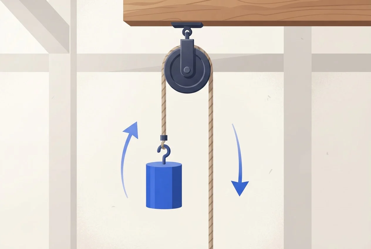
T − mg = ma and mg − T = ma are the same equation with the sign flipped. Choose the direction the object accelerates as positive, then write forces along it as plus and the opposing forces as minus. Upward acceleration gives T − mg = ma. Downward acceleration gives mg − T = ma.
Circular motion follows the same rule, because the acceleration points to the centre. For a mass m on a string moving at speed v on a circle of radius r:
- At the bottom, tension points up towards the centre and weight points away, so T − mg = mv²/r.
- At the top, both tension and weight point down towards the centre, so T + mg = mv²/r.
Can an FBD calculator or generator do this for you?
No. An FBD calculator or generator draws and solves the forces you enter. It cannot decide that the normal force is perpendicular to a slope, that friction points forward on a car's driving wheels, or that tension is smaller than a hanging weight.
Our recommendation: draw by hand first, run the five checks, then use a tool to confirm the final number. Exams give you no tool, and the diagram is where the marks are decided.
Where does the FBD routine pay off in Engineering Mechanics?
Every equilibrium and friction problem in first-year Engineering Mechanics begins with an FBD. The same five checks apply to beams, ladders, wedges and trusses, except that you often draw the object's real shape and place each arrow where the force acts. A dot is enough only when all forces pass through one point.
The habit starts earlier. Laws of Motion in Class 11 Physics is where it forms, and if you are behind, catching up on Class 11 Physics for the Maharashtra Health and Technical Common Entrance Test (MHT-CET) is the place to restart. For the engineering paper, see how to study Engineering Mechanics.
If you want it taught, our Engineering Mechanics course for Savitribai Phule Pune University (SPPU) is taken by Rahul Jewaani (RG Sir) in Hindi. It has structured video lectures covering the complete syllabus, foundational content if you need a basics review, self-paced learning and practice problem sets. As of 10 October 2026 the course is priced at ₹1,699 (listed at ₹1,999 before the discount), and access is valid until 30 June 2027. Padhna Aasaan Hai: run the five checks on every practice problem.
Learn Engineering Mechanics with RG Sir
Frequently asked questions
Sources
- 1.OpenStax University Physics Volume 1, 5.7 Drawing Free-Body Diagrams, OpenStax
- 2.Papadopoulos, Batista Abreu and Santiago-Roman, "How do Students Explain Their Errors in Free Body Diagrams?", American Society for Engineering Education, 2026
- 3.RG Lectures: Engineering Mechanics, Pune University (2026-27), RG Lectures, 10 October 2026
- 4.Our own calculations: the incline, pulley, angled-pull and knot examples, solved with ΣF = ma and g = 9.8 m/s².