First Angle vs Third Angle Projection: The Rule for SPPU
First angle vs third angle projection differ only in where views land on the sheet. First angle puts the top view below the front view, and Pune University drawing problems use it.

By Rahul Jeewani, Founder · Updated 10 Oct 2026

Key takeaways
- 01First angle projection puts the object between you and the projection plane, so the top view lands below the front view and the left-side view lands on its right. Third angle projection puts the plane between you and the object and reverses both.
- 02Ask one question for every view: which way did I look from? First angle places the view on the opposite side, and third angle places it on the same side.
- 03Read the projection symbol from its circles. Circles to the right of the cone profile mean first angle, and circles to the left mean third angle.
- 04SPPU drawing problems are set in first angle, so check every sheet against the five tests below before you submit it.
- 05Both systems draw the same views and only swap their positions. In our worked example, a block of 60 × 30 × 40 mm needs a 110 × 90 mm area of sheet either way.
- 06As of October 2026, the Engineering Graphics end-semester paper is 60 marks, so each unit's drawing practice counts. Spend your time on numericals once the layout rule is automatic.
In this article
- 1What is the difference between first angle vs third angle projection?
- 2How do you work out the view positions without memorising the table?
- 3Does third angle projection change the drawing, or only where it sits?
- 4How do you read the first angle projection symbol?
- 5Which projection method does your exam or your drawing use?
- 6What should you check on every first angle projection sheet?
- 7How do you get enough first angle projection practice before the exam?
- 8Frequently asked questions
Third angle projection puts each view where your eye expects it, which is why first angle feels backwards the moment you learn both. The syllabus does not let you skip the backwards one. Two of the five units in the Savitribai Phule Pune University (SPPU) 2024-pattern Engineering Graphics syllabus name first angle projection. Unit I covers lines and Unit IV covers orthographic views, per the revised SPPU syllabus.
That is why students memorise a placement table, lose it under exam pressure, or reverse the symbol, since the first angle and third angle symbols look almost identical. A table is the wrong tool for this. One question rebuilds the layout every time, and it works the same whether you are in an exam hall or at a drawing board.
Below you get that question, a measured example showing the two systems are mirror images, a symbol test that works from the geometry, and a five-point sheet check. Padhna aasaan hai once the rule is clear.
What is the difference between first angle vs third angle projection?
First angle projection places the object between you and the projection plane, so each view lands on the side opposite to where you looked from. Third angle projection places the plane between you and the object, so each view lands on the same side you looked from. The views themselves are identical. Only their positions on the sheet change.
The front view stays in the middle in both systems. Everything else moves around it:
| You look at the object from | First angle puts that view | Third angle puts that view |
|---|---|---|
| Above (top view) | Below the front view | Above the front view |
| Its left (left-side view) | To the right of the front view | To the left of the front view |
| Its right (right-side view) | To the left of the front view | To the right of the front view |
| Below (bottom view) | Above the front view | Below the front view |
The Bureau of Indian Standards (BIS) publishes the drawing practice SP 46. It gives the first angle placements in the same terms. The view from above goes underneath the front view, and the view from below goes above it. The view from the left goes on the right, and the view from the right goes on the left. Third angle reverses each of these. Autodesk's drawing documentation says the same: in first angle, views placed to the right of a base view show the object as seen from the left, while in third angle they show it as seen from the right.
How do you work out the view positions without memorising the table?
Use one question for every view: which way did I look from, and does my system put the view on the opposite side or the same side? First angle answers "opposite". Third angle answers "same". The question rebuilds the whole table in about ten seconds.
- Draw the front view first and leave it where it is.
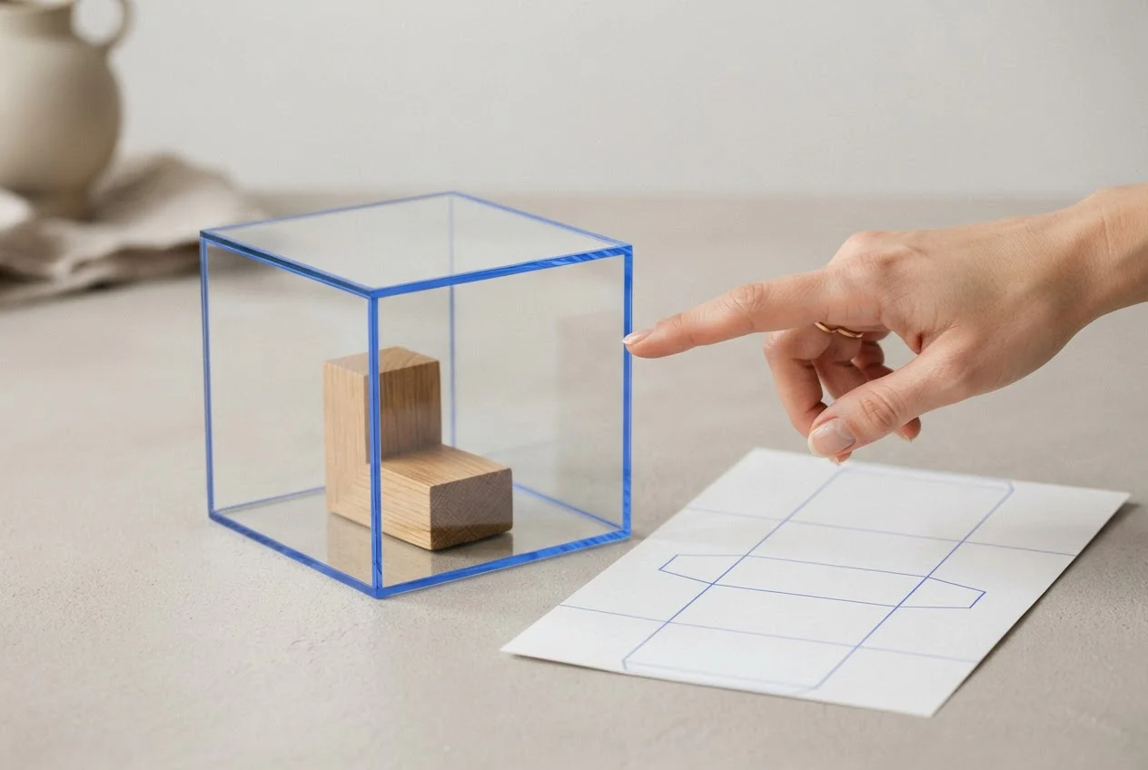
- Name your system. In first angle the object is nearest to you and the plane sits behind it, so the object comes first and the view is pushed to the far side. In third angle the plane sits between you and the object, so the view is pulled toward you.
- Take the view you need and note which way you looked from.
- Place the view on the opposite side (first angle) or the same side (third angle).
Test it on the top view. You looked from above. First angle says opposite, so the top view goes below the front view. Third angle says same, so it goes above. Test it on the left-side view. You looked from the left. First angle puts it on the right, and third angle puts it on the left. Both answers match the table.
Does third angle projection change the drawing, or only where it sits?
Only the position changes. We checked this with a block where W = 60 mm (width), D = 30 mm (depth) and H = 40 mm (height), using a 20 mm gap between views. The three views are the front, top and left-side view. This is our own calculation on arbitrary dimensions, and it uses the outline box of each view (the rectangle that just encloses it).
- Top view: its centre sits H/2 + gap + D/2 = 20 + 20 + 15 = 55 mm from the front view's centre. It is 55 mm below in first angle and 55 mm above in third angle.
- Left-side view: its centre sits W/2 + gap + D/2 = 30 + 20 + 15 = 65 mm from the front view's centre. It is 65 mm to the right in first angle and 65 mm to the left in third angle.
- Space on the sheet: the three views together are W + gap + D = 60 + 20 + 30 = 110 mm wide and H + gap + D = 40 + 20 + 30 = 90 mm high. This is the same in both systems.
So the choice never affects whether your drawing fits the sheet. If you can draw one layout, flipping the top view above or below the front view, and the side views left or right, gives you the other. Each view keeps its own shape.
How do you read the first angle projection symbol?
The symbol is the front view of a truncated cone (a cone with its tip cut off) drawn beside its left-side view, which shows as two concentric circles. If the circles sit to the right of the cone's profile, the drawing is first angle. If they sit to the left, it is third angle.
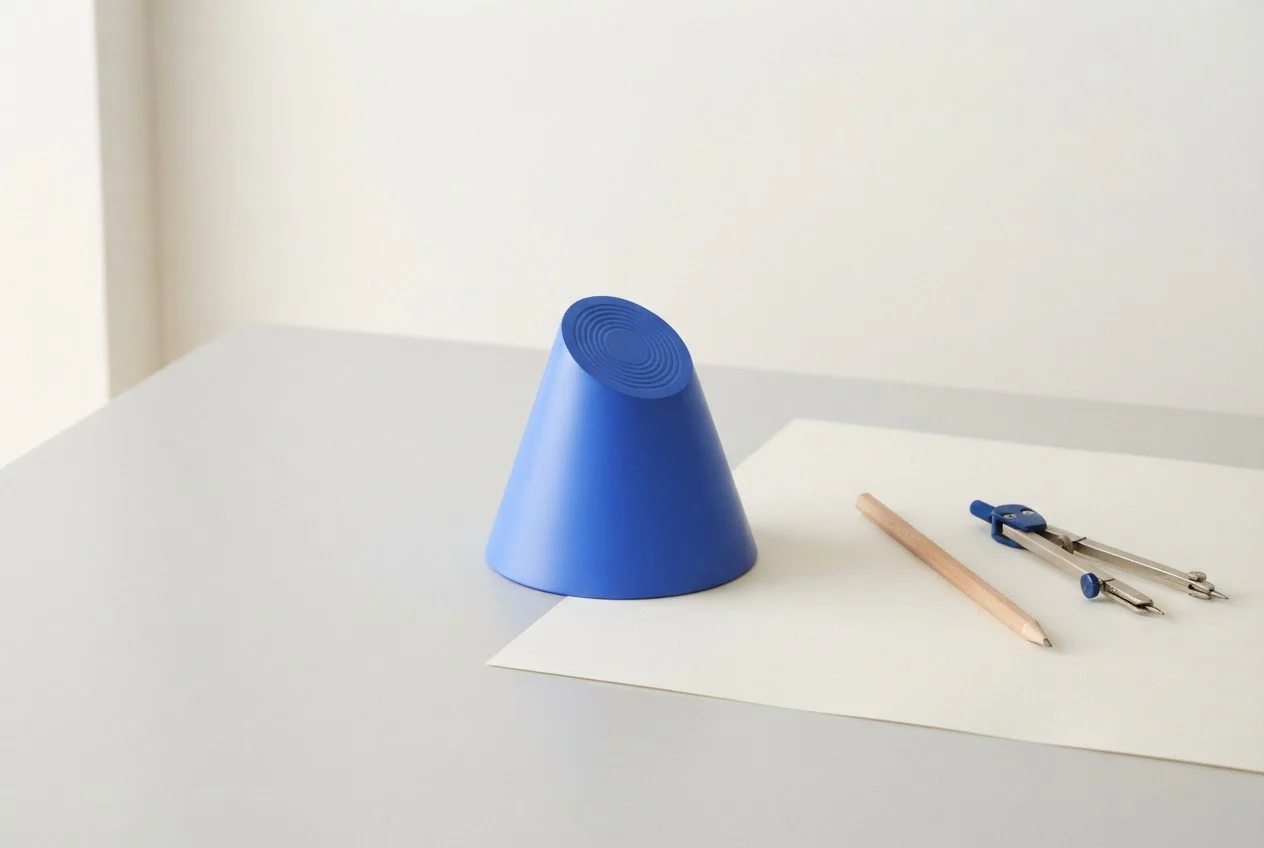
The geometry explains why. In first angle the left-side view goes to the right of the front view, so the circles land on the right. In third angle the left-side view goes to the left, so the circles land on the left. A second check agrees: in the first-angle symbol the trapezoid's shortest side faces away from the circles, and in the third-angle symbol it faces towards them.
Work the symbol out from the left-side view each time: first angle puts the circles on the right, third angle on the left. When you sketch the symbol in an exam, derive it that way instead of recalling a picture.
Which projection method does your exam or your drawing use?
SPPU drawing problems use first angle, and so does Indian drawing practice. As of October 2026, the revised SPPU 2024-pattern syllabus lists "First and Third angle method of projection" in Unit IV and then "Typical problems by first angle projection method". It also marks Unit I's problems on a line inclined to both reference planes as first angle. The revised syllabus is the authority for your exam, so follow your department's copy if it differs. For a unit-by-unit view of where the marks sit, read our guide to Engineering Graphics marks at SPPU.
For Indian drawings in general, BIS SP 46 calls the first and third angle methods "of equal standing" and then states: "as a basic requirement, use of first angle projection method is to be followed."
Other countries set their own default. First angle is the default under ISO (the International Organization for Standardization) and in most of Europe and Asia. Third angle is the default in the USA (ASME Y14.3-2003), Japan (JIS B 0001:2010) and Australia (AS1100.101). ASME is the American Society of Mechanical Engineers and JIS is Japanese Industrial Standards. CAD (computer-aided design) software follows the same split: drawings built to ISO default to first angle and ASME drawings to third angle. Whichever system a drawing uses, read the symbol first.
What should you check on every first angle projection sheet?
Run these five tests before you hand in a sheet. Each has a pass and a fail.
Symbol
Pass: the circles sit to the right of the cone profile. Fail: they are on the left, or the symbol is missing.Top view position
Pass: the top view sits directly below the front view. Fail: it sits above.Side views
Pass: the left-side view is to the right of the front view and the right-side view is to its left. Fail: either is swapped.Alignment
Pass: each vertical edge in the front view lines up with its partner in the top view along a projector line. A projector line is the thin line that carries a point from one view to another. Every height in the front view must also line up with its partner in the side view. Fail: any edge is off its projector line.One system per sheet
Pass: every view obeys first angle. Fail: any view was placed by third angle habit.
Our recommendation: do tests 2 and 3 first, because swapped placement is the quickest way to lose marks on a sheet that is otherwise correct.
How do you get enough first angle projection practice before the exam?
Draw the same object in both systems, check each placement against the one-question rule, and repeat until the layout needs no thought. Then spend your time on numericals (calculation-based drawing problems). As of October 2026, the revised SPPU 2024-pattern syllabus (from academic year 2025-26) gives Engineering Graphics a 60-mark end-semester paper, 40 marks of Comprehensive Continuous Evaluation (CCE, the in-semester assessment) and 25 marks of term work (marks for your practical sheets and journal), per the revised SPPU syllabus. Unit IV is one of five units of six hours each.
Our Engineering Graphics course for Pune University is taught by Rahul Jewaani (RG Sir). It starts from scratch and covers theory, numericals and practicals, including AutoCAD. As of October 2026 it costs ₹1,399 against a list price of ₹1,799.
Drawing is only one of your first-year subjects. Engineering Mechanics is another that Rahul Jewaani teaches, so our guide to how to study Engineering Mechanics helps you plan it. If you are still deciding what to take, first year engineering classes in Maharashtra compares your options. When you are ready, see the courses in our store.
Learn Engineering Graphics for Pune University
Frequently asked questions
First, second, third and fourth angle are the four quadrants formed by the horizontal and vertical planes. Second and fourth angle are not used because, once the planes are folded flat, the views overlap or one comes out flipped, which is too confusing to read on a drawing. See the multiview projection overview.
Sources
- 1.SPPU First Year Engineering 2024 Pattern syllabus, Revised 2025: Engineering Graphics marks and Units I and IV
- 2.Bureau of Indian Standards, SP 46: Engineering Drawing Practice for Schools and Colleges, clause 8.2.2 (1988 edition)
- 3.Autodesk Help: first-angle and third-angle projection in drawings
- 4.Wikipedia: Multiview orthographic projection (symbol description, regional standards, why second and fourth angle are unused)
- 5.RG Lectures: Engineering Graphics, Pune University course