Orthographic Projection: Draw Three Views, Find the Missing One
Orthographic projection draws an object as separate flat views. Pune University problems use first angle, where the top view sits below the front view, and shared dimensions give any missing view.

By Rahul Jeewani, Founder · Updated 10 Oct 2026

Key takeaways
- 01Orthographic projection shows an object as flat views. In SPPU's 2024 course you draw typical orthographic problems in first angle: top view below the front view, right-side view to its left.
- 02Front, top and side views share dimensions in pairs, so every missing-view question can be solved by carrying those shared dimensions across.
- 03Two views can describe more than one object. In our worked example, the largest solid that fits the front and top views has 24 cubes, and the real object has 16.
- 04Run six pass-or-fail tests on your sheet before submitting: alignment, shared dimensions, edge accounting, hidden features, line priority, and layout with the first-angle symbol.
In this article
- 1What is orthographic projection, and why does it need several views?
- 2Which projection angle should you use in SPPU, and where does each view go?
- 3What do the three views of a real object look like in first angle?
- 4How do you find a missing view in orthographic projection?
- 5How can you check an orthographic drawing before you submit it?
- 6How do orthographic and isometric projection differ, and why do both appear?
- 7How should you practise orthographic projection so it sticks?
- 8Frequently asked questions
Orthographic projection is one of five equal units in the Savitribai Phule Pune University (SPPU) 2024 Pattern Engineering Graphics course, taking 6 of its 30 teaching hours. Even so, it is the unit where a drawing can look finished and still be wrong.
The clearest example is a view placed on the wrong side of the front view. Every line in it can be correct, yet the sheet reads as the wrong projection system because the layout rule was swapped. A top view drawn above the front view, copied from material written for a different projection system, is one way it happens. In our experience, a missing dashed line or a side view that disagrees with the top view costs marks in the same way.
All three slips are checking problems, not talent problems. The layout rule is short and the test for a missing view is mechanical, so once you know both you can run the same steps on every question and catch an error before the examiner does.
What is orthographic projection, and why does it need several views?
Orthographic projection draws an object by looking straight at it along lines perpendicular to the drawing plane, with no perspective. Edges parallel to the drawing plane show their true length, and inclined edges look shorter. Each view shows only two of the three dimensions, so you need several views to describe the object.
The three main views are:
- Front view: shows width and height.
- Top view: shows width and depth.
- Side view: shows depth and height.
An object has six possible principal views (front, back, top, bottom, left and right), as Engineering LibreTexts sets out. In practice you draw the two or three that show every feature.
Which projection angle should you use in SPPU, and where does each view go?
Use first-angle projection. SPPU's 2024 Pattern Unit IV covers the first and third angle methods of projection and sets typical problems by the first angle method, and lines inclined to both reference planes in Unit I are also drawn in first angle (SPPU First Year Engineering 2024 Pattern syllabus). Learn third angle too, because Unit IV lists both.
| View | First angle (your sheet) | Third angle |
|---|---|---|
| Top view | below the front view | above the front view |
| Right-side view | left of the front view | right of the front view |
| Left-side view | right of the front view | left of the front view |
| Side of the object facing the front view | its back | its front |
First angle feels backwards because the object sits between you and the drawing plane, so each view lands on the opposite side from where you looked. In third angle the plane sits between you and the object, so each view lands next to where you looked, as Engineering LibreTexts explains.
Use the last row of the table as a self-check. In first angle, the edge of the top view nearest the front view is the back of the object, and so is the edge of the side view nearest the front view. If your sheet disagrees, the views are swapped.
Material written for American courses uses third angle, so check the projection symbol before you copy a layout from it.
What do the three views of a real object look like in first angle?
For the example object below, the front view is two tall stubs with a low notch (8 squares), the top view is a 4 by 3 rectangle (12 squares) and the right-side view is an L-shape (5 squares) placed to the left of the front view.
The object is a base slab 4 units wide, 3 deep and 1 high, with a wall 4 wide, 1 deep and 2 high along its back edge. A slot 2 units wide is cut through the full height of the wall in the middle. Counted as unit cubes, that is 12 in the slab plus 4 in the two wall stubs, 16 in all.
First-angle layout, one character per unit square:
 RIGHT VIEW      FRONT VIEW
   ..#            #..#
   ..#            #..#
   ###            ####

                  TOP VIEW
                  #::#
                  ####
                  ####
- Front view: 3 + 1 + 1 + 3 = 8 squares. No dashed lines are needed, because the slot runs straight through the wall.
- Top view: 12 squares. In the back row the two middle squares (::) are the slot floor, bounded by a line on each side.
- Right-side view: 5 squares, with the tall part on the right. That is the back of the object, next to the front view, as the table says it should be.
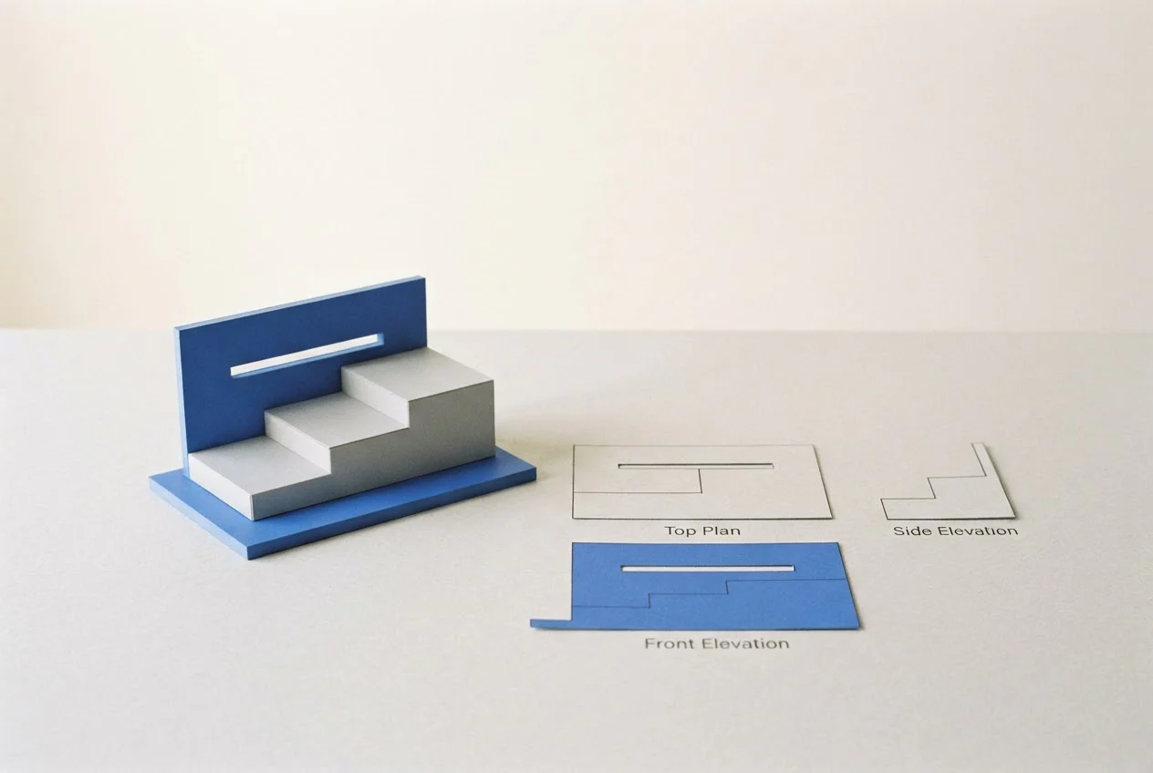
Two views can describe more than one object. This is our own model, worked out for this one object. The largest solid consistent with the front and top views fills every position that appears in both, which is 8 front squares × 3 units of depth = 24 cubes. Adding the right-side view removes the 8 cubes in the two front rows that stand above the slab, leaving 16, which is the real object.
So for this object, a third view settles which solid is meant. Many exam parts are simple enough that two views suffice, but when a question says "draw the missing view", check whether the given views are enough before trusting your first reading.
How do you find a missing view in orthographic projection?
Find a missing view by carrying shared dimensions across the views you have. The front view and top view share width, the front view and side view share height, and the top view and side view share depth. Work in this order, in first angle:
- Name the views you are given and the one you must draw.
- Mark the shared dimensions between the given views and the missing one.
- Draw the empty outline for the missing view in its first-angle position (see the table above).
- Project every vertical edge down from the front view into the top view, and every horizontal edge across from the front view into the side view, using thin construction lines.
- Carry depth between the top and side views with a 45-degree line. Extend the side view's edge nearest the front view downwards, and the top view's edge nearest the front view sideways, until they meet. Draw a 45-degree line from that corner down and away. Run a depth horizontally from the top view to the line, then straight up (or the reverse) into the side view.
- Draw visible edges as continuous lines and hidden edges as dashed lines. Where a dashed and a continuous line coincide, draw the continuous one.
- Check that the back of the object faces the front view, in both the top and side views.
- Add the first-angle projection symbol and the dimensions the question asks for.
A rough isometric sketch helps you test one reading of the object. If two views allow more than one object, ask whether a third view is given, or state your assumption on the sheet.
How can you check an orthographic drawing before you submit it?
Check an orthographic drawing with six tests, each with a pass or fail result you can see on the sheet. Run them before you hand the sheet in.
Alignment
Draw a vertical line through any vertical edge of the front view and extend it through the top view. Pass: every matching edge in the top view lies on that line. Fail: any edge is off the line.Shared dimensions
Measure width in the front and top views, height in the front and side views, and depth in the top and side views. Pass: each pair is equal. Fail: any pair differs.Edge accounting
Pick every edge in one view and find it in another view, either as an edge or as a line seen edge-on. Pass: each edge appears at least twice across the sheet. Fail: an edge appears in only one view.Hidden features
List every hole, slot and step you cannot see from a given direction. Pass: each is dashed in the views where it is hidden. Fail: any hidden feature is missing a dashed line.Line priority
Find places where dashed and continuous lines overlap. Pass: only the continuous line is drawn. Fail: both are drawn.Layout and symbol
Apply the last row of the placement table, and look for the first-angle symbol on the sheet. Pass: the back of the object faces the front view in both neighbouring views, and the symbol is present. Fail: either is missing.
How do orthographic and isometric projection differ, and why do both appear?
Orthographic projection gives several flat views with true lengths on edges parallel to the plane, while isometric projection gives one pictorial view that shows three faces at once. Both appear together because SPPU's isometric unit asks you to build an isometric view from given orthographic views.
The syllabus order makes this explicit. SPPU's 2024 Pattern places Isometric Projection (Unit V, 6 hours) straight after Orthographic Projection (Unit IV, 6 hours), and Unit V covers the isometric scale and constructing isometric views from given orthographic views (SPPU syllabus). The course outcomes say the same: outcome 4 is drawing several 2D views of an object, and outcome 5 is drawing an isometric projection from given orthographic views (SPPU course outcomes).
If you cannot go from three views to a picture and back, both units suffer. Our Engineering Graphics guide shows where the marks sit across the units.
How should you practise orthographic projection so it sticks?
Practise by going from object to views and back, and by running the six tests on every attempt. We recommend short daily sessions of about ten minutes with a model over one long weekend session.
- Hold an object. Use an eraser with a notch cut in it, a matchbox or clay. Turn it to the front, top and side before you draw anything.
- Draw views from an isometric sketch. Then rebuild a rough isometric from your own three views. If it does not match the original, one of the views is wrong.
- Cube-count your answer. Count the unit squares in each view, like the 8, 12 and 5 squares in the slotted-wall example, then confirm that your reading of the object reproduces all three views.
- Time the missing-view routine. In an exam you have limited time for one question, so practise the eight steps until you do not need to think about the order.
If you want the whole chapter taught step by step, our recorded Engineering Graphics course for Pune University covers theory, numericals, practice sets and AutoCAD practicals. Rahul Jewaani (RG Sir) created it, with Amey Sir as the Engineering Graphics faculty. As of October 2026 the recorded course is ₹1,399 (listed at ₹1,799 before the current discount). If you are still choosing what to take in first year, our first-year engineering roadmap covers the other subjects.

Learn Engineering Graphics step by step with RG Lectures
Frequently asked questions
Sources
- 1.Savitribai Phule Pune University, First Year Engineering 2024 Pattern syllabus, Engineering Graphics (ESC-103-MEC)
- 2.Savitribai Phule Pune University, First Year Engineering (2024 course) subject-wise course outcomes
- 3.Engineering LibreTexts, Orthographic projections (Illinois Institute of Technology)
- 4.RG Lectures, Engineering Graphics for Pune University